周辺光量比、ロールオフ、口径食
本ページはイメージングリソースガイドのセクション3.2です
周辺光量比やロールオフ、また口径食 (イメージングレンズの縁を通る光線が物理的事由に遮られる現象)といった問題を解決するために、センサーフォーマットを考えていかなければなりません。センサーやセンサーフォーマットに関する更なる情報は、センサーに解説しています。
センサーとレンズを一致させる
時折持ちあがる問題の中に、センサーサイズに対するイメージングレンズの対応能力の問題があります。レンズデザインに対して使用するセンサーのサイズが大きすぎる場合、結果として得られる画像は、視野の周辺に向かうほど暗くなっているか、或いは周辺部の画像が全く存在しないかのいずれかです。この現象は、口径食によって引き起こされます。システム解像度に対する要求が高くなると、センサーの画素サイズをより小さくするか、或いはセンサーサイズ自体をより大型化していくかのどちらかの検討を始めます。MTFや回折限界に関するセクション (エアリーディスクと解像限界 & 変調伝達関数 (MTF))で詳細を解説した通り、画素サイズの小型化への流れは、物体の真のディテールを解像する光学的能力に関係した諸問題を引き起こします。この問題や、現在のセンサー技術が引き起こしたS/Nや感度に関係した問題は、センサーサイズを大型化していくきっかけとなり、適切なレンズを使用しない限り生じる口径食やロールオフといった新たな問題を引き起こしています。
周辺光量比

Figure 1: X軸にイメージセンサーフォーマットを示したRI曲線
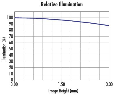
Figure 1に代表的なRI曲線 (像高と相対的な明るさの関係) を示します。個々の曲線は、Fナンバー別のRI性能を表します。RIは明るさの絶対値を表しているわけではなく、Fナンバーを高くしていくほど全体的な明るさは依然として減少します (Fナンバーに関する詳細はシステムスループット、 Fナンバー、開口数を参照)。X軸はセンサーの中心からコーナーへの距離を表します。Y軸は明るさの最大値が得られる地点 (通常は視野の中央) を100%とした場合の視野内のあらゆる地点での明るさの相対比です。センサー別のレンズのRI性能を規定するために、センサーの対角長を表す点線状の縦線が挿入されます。Figure 2 は、Figure 1 に紹介したF1.4でのRIを画像投影したものです。

Figure 2: F1.4の青色曲線が2/3型センサーでどのような明るさの分布になるか
Figure 1の曲線中の青線は、レンズの絞りを最大開放にして、F1.4に設定した時のものです。このレンズでは、⅔型センサーのコーナー部での光量レベルが57%のRIになることがわかります。同じ条件下で、1/2型センサーのコーナー部でのRIは72%です。センサーサイズを小さくするとRIは改善します。Fナンバーを高くすると、レンズに口径食が生じるまでRIは改善し、口径食が生じるまではどの高Fナンバー時においても明るさの分布が同じになります。レンズのFナンバーを高くしていっても、イメージサークルサイズが増えることはありません。特定センサーサイズに向けてデザインされたレンズというのは、Fナンバーをステップダウンさせても、それより大きなセンサーサイズには有効に機能しません。
ロールオフは、レンズの絞りをステップダウンしていっても引き続き起こります。レンズに入る光線の入射角度に関連していて、レンズを通過する光線の本数には関係していないためです。レンズの多くは、視野中心部で最も明るく、周辺に向かうに従い暗くなっていく、或いは明るさほぼ変わらないといった照度分布を持っています。イメージサークルに対してRIが徐々に増えていくといったことは非常に稀なケースですが、このケースは瞳補正に関連します (本テキストでは説明を省略します)。
レンズ内の口径食 - 上級
口径食は、イメージングレンズを構成する個々のレンズの縁や機械的絞りによってレンズ系の外側を通る光線が遮られ、センサーに最終的に辿り着くことができない結果起こります。この光線の遮断は、意図的にも偶発的にも行え、また場合によっては回避不能であったりもします。口径食の現象は、低Fナンバー設定時や短い焦点距離のレンズ、或いは低コストで高解像力を実現する使命を持ったレンズに多く見られます。Figure 3.9は、同じf=16mmのレンズを異なるFナンバー設定 (F1.8とF4)で使用した時に生じる遮光の様子を表わします。
Figure 3では、遮られた光線を赤丸で図示しました。図をご覧の通り、光線の一部は、レンズ系内の全ての光学素子を通過することなく、途中で遮られてしまっています。対するFigure 3bでは、この現象が生じていません。Figure 3aの口径食は、光学素子の直径の制限や、一部の光線を遮ることで迷光の透過を遮断するなどの幾つかの理由が考えられます。何か目的があって口径食が生じるようレンズ系をデザインし、レンズの全体性能を改善したり、或いはコストを削減したりするといったことがあります。


Figure 3: 6mmレンズデザインをF1.8 (a)とF4 (b)で設定した時の光路図: F1.8では口径食が生じ、光線の一部がレンズの縁によって通過を遮られている
口径食で性能を高める (口径食の選択) - 上級
口径食は、イメージサークル全体にわたりレンズデザインの解像力を最大化するのに用いられます。画像周辺部を形成する光線をセンサー上の所望の場所に向けるといったことは難しいため、物体のより細かい部分を画像の中心部ではなく、周辺部で再現することは通常難しくなります。また本来入射すべき画素ではない間違った画素に入射する光線は、その場所での画質を低下させます。これを避けるための一つの方法は、システムからこうした迷光を取り除いてしまうことです。不要な光線がセンサーに届くことがなければ、その光線は画質は損ねません。なおこの光線を取り除くことは、周辺光量を低下させることに繋がります。
Vignetting at the Pixel Level: Large vs. Small Pixels
Figure 4 illustrates light rays incident on a pixel in the corner and center of a sensor at f/1.4 (a and b) and f/2.8 (c and d). In Figure 4a, some light spills onto the adjacent pixel creating slight image and contrast degradation. Increasing the f/# (Figure 4c) essentially creates vignetting which clips those extraneous rays and improves image contrast. Figure 5 illustrates this same vignetting effect with smaller pixels. However, with the larger pixels in Figure 4, the change in f/# has much less of an effect on the overall image quality, because it occurs over a smaller number of pixels.

Figure 4: Light rays incident pixels in the corner of a sensor at f/1.4 (a and b), and f/2.8 (c and d). Increasing the f/# creates vignetting which clips the extraneous rays spilling onto the adjacent pixel in (a) and improves contrast.
In Figure 5, the pixels have been reduced to half the size, yielding a 4X resolution increase. In this example, vignetting by increasing f/# greatly, improves performance across the entire sensor, as opposed to the first example which only slightly improved the imaging performance in the corner of the image.

Figure 5: Light rays incident on pixels in the center of a sensor at f/1.4 (a and b), and f/2.8 (c and d). For large pixels, increasing the f/# has a less significant effect on image quality as all rays were nearly contained in the desired pixel. For small pixels, increasing the f/# creates vignetting which prevents the extraneous rays from spilling onto nearby pixels.
Figures 4 and 5 exhibit nominal design capabilities and do not account for reduced performance that results from manufacturing tolerances. With tolerances included, the need for vignetting can be even more pronounced, especially in cases where cost is a driving factor.
Vignetting can also be purposefully designed into lenses in scenarios in which the effects from manufacturing tolerances adversely affect the control of rays, causing image degradation. The looser the tolerances on the lens, the more adverse these degrading effects can become, and tightening the tolerances is often not practical due to the increase in manufacturing cost. Often, a balance must be struck between reducing manufacturing cost and maintaining image quality. In cases where cost is a primary factor, vignetting must be utilized in an attempt maintain resolution across the field of view. Doing such will have an adverse effect on the illumination profile. Designing vignetting into a lens can be accomplished in a couple different ways: by purposefully designing the clear apertures of the individual lens elements such that they vignette severely off-axis rays, or by introducing mechanical apertures to block aberrated rays, as shown in Figure 8a.
Vignetting in Different Lens Designs - ADVANCED
Figure 6 features a standard 12mm Lens design layout, along with both its relative illumination and MTF curves. Note the size difference of the ray bundles in 6a at the center (blue lines) and corner (green lines); the size difference demonstrates a large amount of selective vignetting. The vignetting leads to lower illumination at the edges of the image than in the center (6b). This is done to minimize the costs associated with materials and manufacturing tolerances, while maintaining reasonable performance at a lower price.


Figure 6: A standard 12mm lens ray path (a), relative illumination curve (b), and MTF curve (c).
The lens in Figure 7, an ultra-high resolution 12mm lens design, has a much more evenly sized ray bundles across the field (7a) due to a low level of vignetting. This translates to much more even relative illumination across the entire sensor (7b). The lens in this example is designed using more costly materials at tighter tolerances, which allows it to maintain high levels of performance across the image, without the need to introduce vignetting to improve its performance. The trade off in using such a lens is that the ultra-high-resolution lens is more expensive than the standard design.


Figure 7: An ultra-high-resolution 12mm lens ray path (a), relative illumination curve (b), and MTF curve (c).
照明のロールオフ - 上級
ロールオフは、視野に対するRIの減少ですが、口径食からではなく、放射則から引き起こされます (Figure 8)。最も単純な構成の場合、口径食がない時のレンズで得ることのできるイメージサークルの最大輝度は、像空間内の主光線角度のコサインの4乗の大きさで制限されます。これは、照明のコサイン4乗則として知られます。

Figure 8: ロールオフは、口径食が原因ではなく、放射則によって生じるフィールド内での周辺光量比の減少
Figure 9に、像側中心と同コーナー側の主光線を各々示します (赤線で図示)。ロールオフは、アプリケーションの多くにおいて問題となることは通常ありませんが、主光線角度が非常に大きくなる場合には問題となる場合があります。特に大判センサーやラインセンサーを利用したアプリケーションや、視野が広角な (焦点距離が短い) アプリケーションではその傾向が高くなります。

Figure 9: イメージングレンズのレイアウト: 画像中心部に像を結ぶ光束 (青線) と同コーナー部に像を結ぶ光束 (緑線) の各々の主光線を赤線で図示。この赤線間の角度がロールオフを推量するのに用いられる
Table 1は、主光線角度が大きくなるとロールオフがどれだけ増加するかを表します。15°の角度では、画像の中心からコーナーにかけたRIの減少は13%ほどだったのに対し、角度が2倍になると、RIが44%近く減少するのがこの表から見て取れます。ロールオフは、作動距離が短く、実視野の大きいアプリケーションにおいて考慮されなければなりません。この種のレンズは、センサーサイズに関係なく、像空間側に大きな主光線角度を通常持っています。
| 主光線角度 | コーナー部での最大周辺光量レベル |
|---|---|
| 5° | 98.5% |
| 10° | 94.0% |
| 15° | 87.1% |
| 30° | 56.3% |
| 45° | 25.0% |
| 60° | 6.3% |
Table 1: 画像コーナー部での主光線角度とRIの関係 (画像中心部の光量を100%とした場合)
ロールオフを補正するための一つの方法は、レンズを像側テレセントリック光学系にデザインすることです。これを行うことで、主光線間の角度差が0°となり、均一な明るさを実現できます。別の方法は、検査対象物体側の照明を意図的に不均一な明るさにすることです。検査対象物の端部近くを照らす照明器を追加装備したり、レンズの対物側先端部にアポダイジングフィルターを加えることで、ロールオフを緩和することができます。
ロールオフとマイクロレンズ - 上級
センサーの多くには、有効画素エリアに届く光の量を増やすためにマイクロレンズが利用されます。他の全てのレンズと同様、マイクロレンズには最も効率よく機能するための許容入射角があります。光の入射角がこの許容角度より大きくなると、画素の有効エリア (Active Area) に入る光量が減少します。この問題に対処するため、レンズの多くは像空間側の主光線角度を5~7°程度にして設計されているようです。Figure 10a は画素上に配置されたマイクロレンズの図解です。


Figure 10: ロールオフや周辺光量に影響を及ぼす主光線の入射角度
Figure 10b とFigure 10c は、マイクロレンズに対して垂直入射と斜入射で焦点を結ぶ様子をそれぞれ表します。垂直入射の図は、センサー上の中央画素を表わしています。この位置では、全ての光束が画素の有効エリア (Active Area) に像を結びます。これに対し、斜入射の図では全ての光束が有効エリアに入るわけではありません。これは、レンズのRI曲線で規定される性能を更に低下させる結果となります。


 前のセクション


もしくは 現地オフィス一覧をご覧ください
クイック見積りツール
商品コードを入力して開始しましょう
Copyright 2023, エドモンド・オプティクス・ジャパン株式会社
[東京オフィス] 〒113-0021 東京都文京区本駒込2-29-24 パシフィックスクエア千石 4F
[秋田工場] 〒012-0801 秋田県湯沢市岩崎字壇ノ上3番地